The H6 Downlink
The necessity for a downlink was evident after the crash of the H5 rocket. If in that case a downlink had been present, we would have had data on this fatal flight, from which we probably would have been able to determine the cause(s) of the crash. Fate has it that, with the launch and the subsequent crash of the H6C, the data received from the rocket through the downlink enabled us to determine the location of the crash site and to analyse the flight itself.
The essential parts
The up/downlink system is based on an asynchronous serial connection which enables exchange of data in a set format and a set time frame.Despite the low velocity, there is little time on ground to receive the data, to process it and to store it at the same time. For this reason, a node concentrator has been developed, which controls the up/downlink, independent of the other computers in the ground segment.
The downlink consists (as far as the flight segment is concerned) of a UART (sequencer), which converts the bytes presented to it into an RS-232 signal, an (1200/2200 Hz) FSK modulator and a 2-meter FM transmitter. The sequencer is a microprocessor which samples the data at different frequencies and subsequently stores it in the IRM. A reduced set of data is fed into the transmitter and transmitted through the downlink to the ground station.
The up/down link system is working in a continuous synchronous way: the data flow has a set format and the baudrate is constant. Although the baudrate is quite low, the available PCs have too little time to process the data flow and to store it. This is why the system with the node concentrator was developed.
Data frame
The data frame of the downlink, which is transmitted to the ground station twice per second, is described below.
| Byte
|
Contents
|
Source
|
Description
|
| 1 | HEX 38 ("8") | controller | Control word start downlink |
| 2 | 1xxx.xxxx | controller | Frame counter high byte |
| 3 | 1xxx.xxxx | controller | Frame counter low byte |
| 4 | 1xxx.xxxx | ADC_PT ch.0 | Body pressure |
| 5 | 1xxx.xxxx | ADC_PT ch.1 | Nose temperature |
| 6 | 1xxx.xxxx | ADC_PT ch.2 | Battery voltage |
| 7 | 1xxx.xxxx | ADC_PT ch.3 | Internal temperature |
| 8 | 1xxx.xxxx | ADC_PT ch.4 | Spare (approximately 0 Volt) |
| 9 | 1xxx.xxxx | ADC_GF ch.0 | Acceleration |
| 10 | 1xxx.xxxx | ADC_GF ch.1 | Thrust |
| 11 | 1xxx.xxxx | ADC_GF ch.2 | Bridge excitation voltage |
| 12 | 100.0000 | not applicable | Spare (empty) |
| 13 | 1xxx.xxxx | controller | Integrated acceleration (7 MSB) |
| 14 | 1000.xxxx | controller | System status high byte |
| 15 | 1000.xxxx | controller | System status low byte |
| 16 | 1xxx.xxxx | Status monitor | Status byte A |
| 17 | 1xxx.xxxx | Status monitor | Status byte B |
| 18 | HEX 47 ("G") | controller | Control word stop downlink |
|
|
|
|
|
Node concentrator
The node concentrator controls the up/downlink, collects data from both the ground segment and the flight segment and distributes the collected data to the other computers in the ground segment. The node concentrator operates like an intelligent data buffer and saves time for the other computers in the ground segment in this way. The data collection takes place at a low rate and continuously, while the distribution is performed in bursts at high rate (9600 baud RS-232). The time between the arrival of the data packages can be used to process and/or to store the data. In this way, several computers can perform specialised tasks efficiently without the necessity to consider communication details and the corresponding timing issues. The node concentrator is built around a single board computer (with 6809 microprocessor) is equipped with its own power supply and several different interfaces. Other computers can be connected to the tie-line.
The NCC receives flight data from the flight segment via the UDLIS at a rate of 600 baud, launch segment data (disconnect wires) via the LACS (2 words per second), and commands via a serial port from the FCC (2 words per second). All this data is stored by the NCC in a set format (frame, see 5.3, interfaces) in a double buffer. as soon as a buffer contains a complete frame, the buffer contents is distributed to the different computers in the ground segment via the DDS. This happens at a rate of 9600 baud. While data is being distributed from one buffer via the DDS, the other buffer is being filled with new data.
When of fault conditions (disturbed or damaged receival) occur, complete frames still have to be offered to the ground segment, in which case fault codes are added to the frame.
The NCC has to assure the following points:
- data have to be send to the ground segment via the DDS in the correct format (complete frames) and at the correct rate,
- the transmitter and receiver of the UDLIS must never be activated at the same time,
- whenever the transmitter of the rocket is active, the UDLIS transmitter must be switched off.
Physically, the NCC consists of a BRUTECH B.E.M.-SBC13 single board computer. The NCC is equipped with a 6809 microprocessor (1 MHz), 24 k RAM and 32 k EPROM, 3 parallel interfaces/timers (VIAs, 60 I/O lines) and 2 serial ports. This is more than enough to incorporate the above mentioned functions. The program is coded in assembler (cross-assembler on PC) and is kept very simple: the program has to allow verification point by point and has to be reliable to a high extent. De distribution of the I/Os is as follows:
- VIA-1 connected to UDLIS en LACS (internal use),
- VIA-2 connected to LACS (launch segment) ,
- VIA-3 connected to FCC keyboard,
- USART-1 connected to UDLIS (to flight segment),
- USART-2 connected to DDS (to ground segment) and FCC .
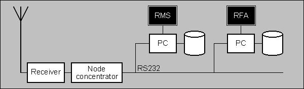
The node concentrator converts the radio signal into an RS-232 signal, which can be directly fed into the serial port of a computer. Two computers were connected; one computer which runs the Rocket Monitor System (RMS) and functions as the launch and flight controller and a second computer which runs the Rocket Frame Analyzer (RFA) and displays the technical information processed from the received flight data on the screen.
The uplink still is an experimental status and the data sent up to the rocket is transmitted down again to the ground station. The node concentrator acts as a slave of the flight segment. In principle, the downlink receiver is always switched on. Only after receiving certain key words can the uplink transmitter be turned on for a very short moment.
52,1KB