The H8 Aerodynamic design
|
|
This page describes the aerodynamics of the H8 project. Read why the canard control was chosen en how the stability margins are calculated. |
- Canard control
- Wing control
- Tail-fin control
Canard control is a small lifting surface in the front area of the rocket. This means that a positive deflection or rotation of the canard (positive about the out-going hinge axis of the right canard looking in forward direction of the rocket) the induced aerodynamic force contributes to the main lift vector of the rocket.
Wing control is generally a larger lifting surface in the neighbourhood of the centre of gravity of the rocket. Advantage is that the main lift-vector can, more or less, directly be canted. However, since the forces are stronger, for the aerodynamic lift of the rocket, the accuracy of the control is much more sensitive. Moreover, due to these forces the hinge-moments might be more significant so that a powerful wing-control system will be required.
In case of a tail-fin controlled configuration the deflection of the surface will cause an aerodynamic force that will be in opposite direction with respect to the main lift vector, since the tail-fin is at the rearward side of the centre of gravity. This means that the aerodynamic force of the tail-fin should acting in a reversed direction compared with the canard at the front, in order to affect the same rotational motion of the rocket.
Since in case of the tail-fin controlled configuration, space is required to build-in the actuators, while at the same time the space would be necessary for the available propulsion system, it was decided to skip the tail-fin option.
For the wing controlled option the risk of having serious deviations in the main vector is much bigger than in case of the canard-configuration. Therefore in the first assessment process the canard-controlled configuration was selected
- Static aerodynamic stability with a global static margin of 1. This means that the resultant of the aerodynamic force will act on the body about one body diameter aft of the centre of gravity.
- A canard deflection should have the right effect. A small deflection must not affect large angles of attack, or the other way around, high deflections should not affect only small angles of attack. A moderate ratio between angle of attack and fin-deflection angle (in trimmed condition) should be in the order of 1 or 2. This means that in trimmed condition a deflection of 1 degree should affect an angle of attack of 1 or 2 degrees.
![]()
where xcp and xcg are, respectively, the distance x of the centres of pressure and gravity on the body axis with respect to the body nose.
Describing the forces and moments in terms of coefficients without dimension:
![]() and
and![]()
with r and v respectively, the air density and velocity, while Sref and Lref are the reference surface and length, the relation between pitching moment coefficient Cm and normal force coefficient CN becomes:
![]()
Roughly for small angles of attack these coefficients are linear dependent with the angle of attack. This can be expressed by using the derivatives to the angle of attack a :
![]() and
and ![]()
So we obtain the relation:
![]()
From this relation it is easy to see, that when the static margin is in the order of 1 and
| (xcp – xcg)/Lref » 1 |
(using Lref as the body diameter) that:
![]()
Going back to the design criterion, that the static margin is about 1, then we see that this implies for small angles of attack that the derivative of the pitching moment coefficient must have the negative value of that of the normal force coefficient. However, since the normal force as function of the angle of attack is mainly dependent on the body geometry including a first ‘guess’ of the tail-fins and the canards, a first order of magnitude for the required pitching moment coefficient can now be obtained.
By decreasing or increasing the tail-fin surface, the relation between Cma and CNa can be fine-tuned. During this iteration-process the canard surface should be kept constant.
Via this process a first estimation of the tail-fin configuration has been obtained. A next step will be the dimensioning of the canard surfaces.
Again, assuming that for small deflection angles the influence of the generated pitching moment is linearly dependent on the canard deflection we can determine the relation for the Cm as follows:
![]()
where d stands for the canard deflection and Cmd is the derivative of the pitching moment coefficient to the canard deflection.
Now, based on the criterion that in a trimmed condition the resulting pitching moment should be zero (Cm=0), we will obtain a relation between the trimmed deflection as function of the angle of attack:
![]()
Since we have expressed the requirement that the relation between (trimmed) deflection and angle of attack should be in the order of 1 or 2 it is clear that the last equation will prescribe a relation between Cma and Cmd . For instance assuming that this relation is about 1 (d t/a t » 1) than
![]()
Again this is a clear criterion to dimension the surface of the canard.
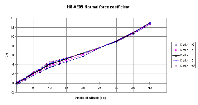
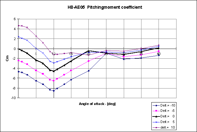
In addition the curves for the normal force and pitching moment coefficients are given as function of the angle of attack a .
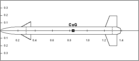
The calculation of the aerodynamic coefficients are based on Mach = 0.6, while Lref = 0.1 m, being the body diameter, Sref = 0.00785 m2 is the body cross-section, and xcg = 0.838 m with full motor mass and body length of 1.38 m.

For comparing the result with the applied process we obtained the following estimations of the aerodynamic values:
![]()
![]()
![]()

Note that these values are based on non-linear effects of the aerodynamic coefficients. A final design will only be obtained in several iteration loops.
