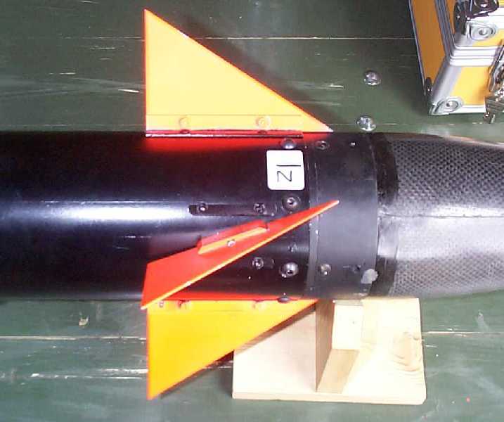
The H8 Canards
34KB
- - Worst case torque to be delivered by the motors, and the duration of pre lift-off condition.
- - Size, dimension and mass constraints for the motors.
- - Accuracy and speed of the motors.
- - Fail/safe operation.
Typically, for modern fin controller systems, electrical servo actuators are used. Servo actuators are compact, closed-loop modules comprising an (electrical) motor and associated gearbox, position/speed sensing device (potmeters/encoders) and an electrical control system that makes the motor drive meet a given position or speed setpoint. Cheap, compact and lightweight servo actuators are widely used in RC model cars and aircraft. Unfortunately, a review of the specifications of these servo's points out that they are not particularly suitable for application as canard controller in the H8. Main objections are:
- they have too large backlash (measured up to 2�) in the gearbox,
- the potentiometers are potentially sensitive to vibration and form part of the control loop, thereby increasing the risk of noise/spikes,
- the high accuracy devices that are available are too big to fit in the half diameter of the rocket body.
- they are controlled by analogue pulse with modulation circuits that are basically inaccurate and sensitive to drift and noise. Professional servo's are very expensive c.q. not affordable and home-designed servo's require complex mechanical construction.
For the H8 an alternative type of motor has been chosen, namely a step motor. Each canard is directly mounted on the rotor of a step motor. The step motor is driven by a dedicated step motor power control circuit. Advantages of the step motor relative to the RC servo's are:
- very accurate positioning and positioning stability (better than 0,1�),
- very fast stepping, typically 1,8 degree in 5 ms,
- simple microprocessor control by providing discrete clockwise/counter clockwise clock pulses.
The stepmotors also have a number of characteristic disadvantages:
- there is no absolute feedback of angular position so if power is lost, the absolute position is lost or at least unknown,
- in order to maintain position the coils or 'phases' have to be powered continuously with requires a high amount of on-board stored electrical energy.
These disadvantages are compensated for by having redundancy in controller power.
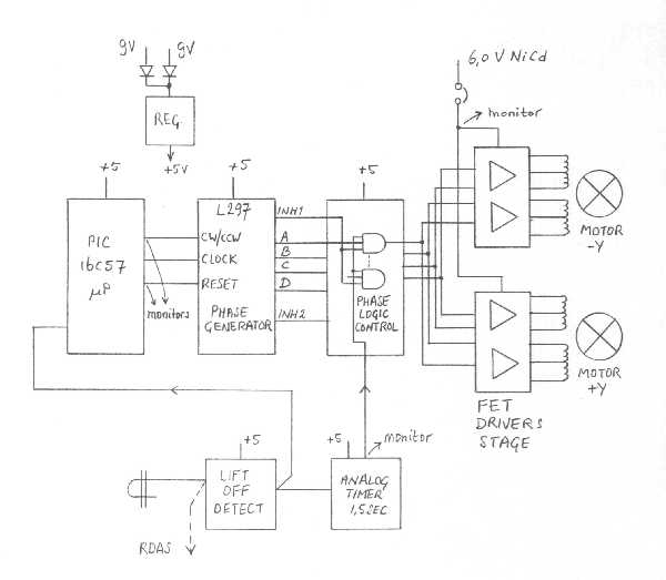
The step motor is from Sany Denki, it is unipolar and delivers a hold-torque of at least 260 mNs (measured 360 mNs) at a phase current of 1,2 A @ 3,6 V). Each motor has two phases and there are two motors, so the battery must be capable of providing 4,8 A current. The battery consists of five 1200mAh high capacity 'penligh-type' NiCad cells. Using very pessimistic assumptions, this battery still provides enough energy to power the motors for at least 10 minutes.
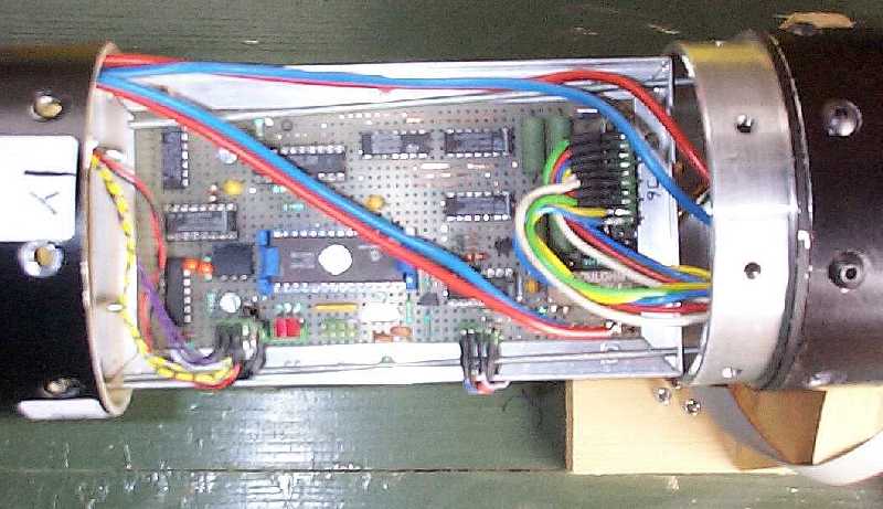
The driver stage for each motor consists of four power MOSFETS with low Rds(on). A well-known controller IC type L297 provides the phase switching signals for the MOSFETS. The L297 clock/reset/direction inputs are controlled by a microprocessor PIC16C57 (same type as used in H7 second stage flight controller). In between the L297 and the gates of the MOSFETS are logic gates that are part of the phase switching logic and allow overruling the L297 pulses with a canard inhibit or 'holding' signal. This signal is generated by an autonomous timer circuit that is triggered upon lift-off of the rocket and it forces the step motors to hold their position during powered flight. At the same time, the microprocessor maintains the hold-state during the rocket motor burning time. Upon calculated burn-out time, the microprocessor internal timer expires and the canard control experiment is initiated.
51KB
- number of deflection steps - how many steps of 1.8o must be made;
- retard time - how many milliseconds between the deflection steps;
- deflection time - how long must the deflection be effective.
The following table shows the used experiment sequence.
|
|
Typically, the response of the rocket to deflection steps of various
amplitudes can be measured, at various velocities. After burn-out the velocity of the rocket decreases at a rate of 10
m/s. Therefore the total experiment time is limited tot some 11 to 12 seconds. Upon reaching the apogeum, the
experiment has to be
finished, because parachute ejection is needed for safe recovery.
5KB